Now that you've learned about logic gates and how they work with binary inputs, let's dive into Boolean algebra. Don't worry if it sounds a bit mathematical – it's actually a simple way to describe and work with the logic we've been talking about. Boolean algebra is named after George Boole, a mathematician who came up with it in the 1800s, and it's the foundation of how computers handle decisions.
At its core, Boolean algebra is a system of maths that deals with true and false values – remember, that's 1 for true and 0 for false, just like in logic gates. It allows us to write down logic expressions using variables and special operators, and then simplify them. This is super useful because it helps engineers design smaller, faster, and cheaper computer circuits by reducing the number of gates needed.
Let's break it down step by step.
Variables in Boolean Algebra
Variables are just placeholders for binary values. We usually use letters like A, B, or C. Each can be either 0 (false) or 1 (true). For example, A might represent whether button A is pressed (1) or not (0).
Operators in Boolean Algebra
There are three main operators that match the logic gates we've seen:
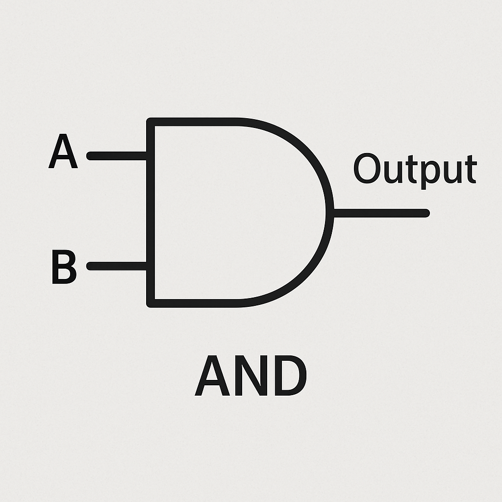
- AND: Written as
A · B (with a dot) or sometimes just AB (no symbol). It means both A and B must be 1 for the result to be 1. Example: If A is 'it's raining' (1 if true) and B is 'I have an umbrella' (1 if true), then A · B means 'it's raining AND I have an umbrella' – only true if both are 1. - OR: Written as
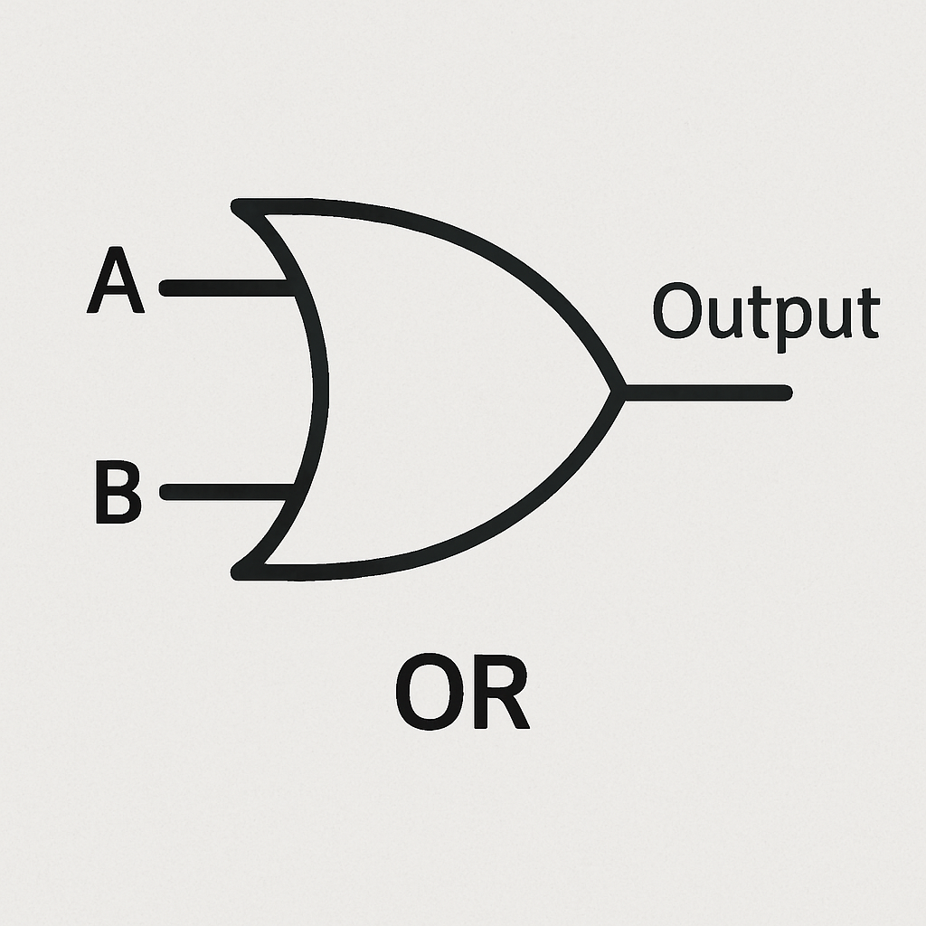
A + B. It means the result is 1 if at least one of A or B is 1. Example: A + B could be 'I can pay with cash OR card' – true if you have either (or both). - NOT: Written as
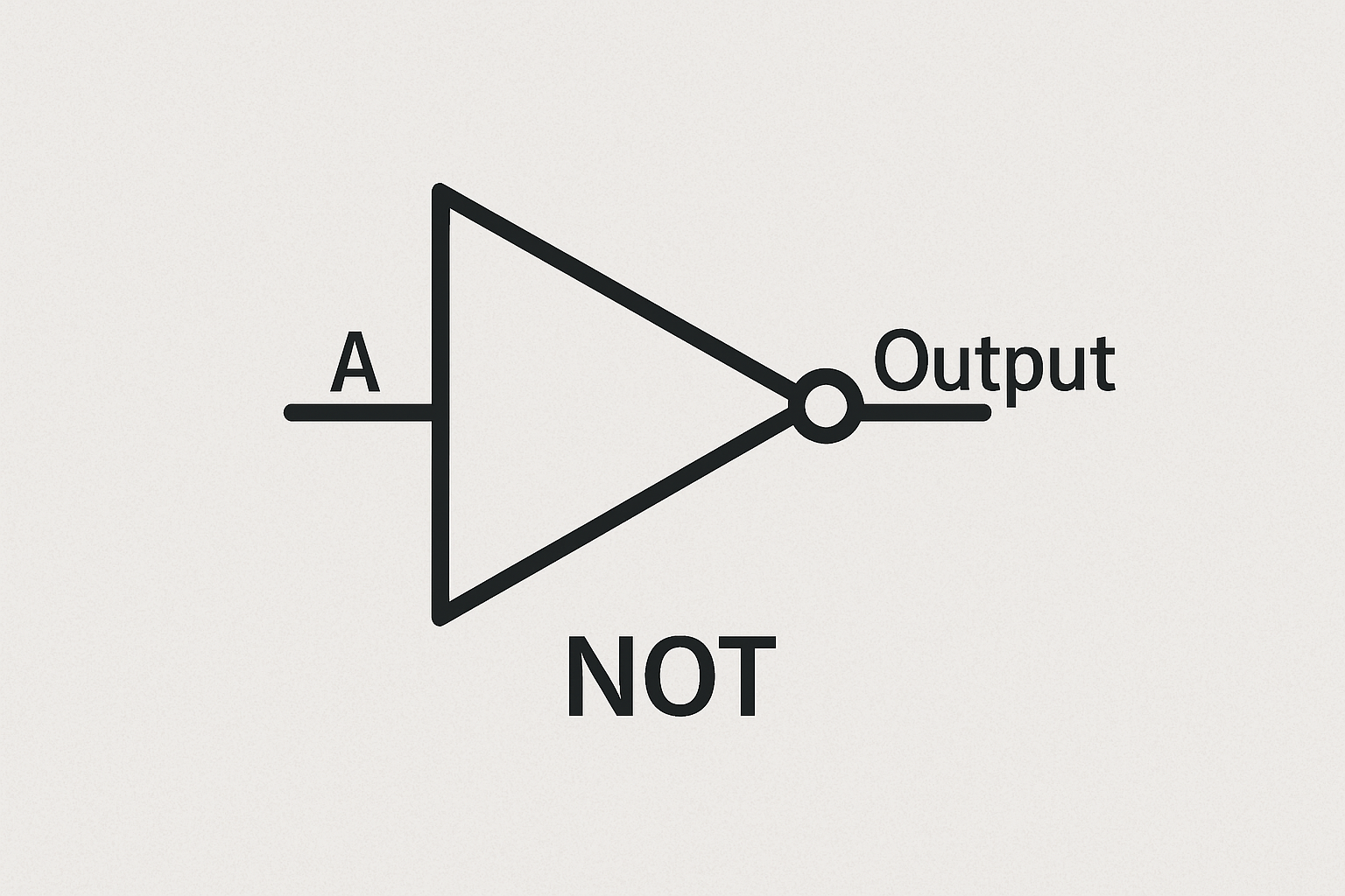
Ā (with a bar over A) or sometimes A'. It flips the value: if A is 1, Ā is 0, and vice versa. Example: If A is 'light is on' (1), then Ā is 'light is off' (0).
You can combine these to make more complex expressions, like (A · B) + Ā, which means '(A AND B) OR NOT A'.
Basic Laws of Boolean Algebra
Just like regular algebra has rules, Boolean algebra has laws that help us simplify expressions. Here are a few key ones explained simply:
- Commutative Law: The order doesn't matter. For OR:
A + B = B + A. For AND: A · B = B · A. Example: 'Apple OR Banana' is the same as 'Banana OR Apple'. - Associative Law: Grouping doesn't matter when you have three or more. For OR:
(A + B) + C = A + (B + C). For AND: (A · B) · C = A · (B · C). This lets you rearrange parentheses without changing the meaning. - Identity Law: Adding 0 or multiplying by 1 doesn't change the value. For OR:
A + 0 = A (like saying 'A OR false' is just A). For AND: A · 1 = A ( 'A AND true' is just A).
There are more laws, like distributive and De Morgan's, but we'll stick to these basics for now. The good part is using these laws to simplify expressions. For example, if you have A · (A + B), using distributive law, it becomes A · A + A · B, and since A · A is just A, it simplifies to A + A · B.
Why does this matter? In real life, simplifying a Boolean expression means you can build a circuit with fewer gates, which saves space and power in devices like your phone or computer.
Take a moment to think about how this connects back to the logic gates. Each operator directly represents a gate: · for AND gate, + for OR gate, ¯ for NOT gate.
 Chromebooks, laptops, and PCs are crucial tools for coding and digital skills education. Chromebooks are ideal for web-based applications and collaborative projects, while laptops and PCs support a wider range of programming environments and software for more intensive tasks like software development and data analysis.
 Let's start with the basics. Computers as super-smart machines that make decisions all the time, but at their core, they use something very simple: yes or no answers. This is where logic gates come in. Logic gates are like tiny decision-makers inside a computer's hardware. They take in simple inputs – which are just binary numbers, meaning 0 (for 'false' or 'off') or 1 (for 'true' or 'on') – and based on those, they produce an output that's also a 0 or 1.